How to successfully design your EV charging System
The UK’s electric vehicle market is continuing to accelerate – and, despite the chip shortage, generally shows little sign of stepping down a gear:
- Europe overtook China to become the biggest market for EVs during the pandemic – making 2020 a record year for electric cars. [1]
- Another car giant, Toyota, has announced it’s to spend $13.6 Billion on EV batteries by 2030, and will further expand its development of battery-powered electric cars.[2]
- New plug-in hybrid and full electric vehicle sales in Great Britain reached 85% of diesel sales by June 2021 and look set to overtake by the end of the year.[3]
These vehicles need to be charged somewhere – and that’s where you come in, with your new EV charging system solution.
When planning your development, it might seem an easy option to gravitate to the cheapest set of components. However, be warned – this could lead to unreliability, the cost of which will far outweigh any initial savings in build.
In particular, good quality power supply, switching components and sockets are key in creating reliable EVSE (Electric Vehicle Supply Equipment).
Read on as we provide an overview of the essential steps required to successfully develop an EV charging system and network.
Throughout this guide, we’ll be covering the development of smart chargers. The reasoning behind this can be found here.
Your Essential Guide to Designing an EV Charging System
Contents:
Step 1. Why You?
Step 2: What type of charger?
Step 3: Picking a target
Step 4: Taking over the world
Step 5: the biology of the charge point
Step 6: EV charging system software
Step 7: Networking
Step 8: Going the extra mile
Conclusion
Step 1: Why you?
This is the very first question you need to be asking yourself from a business perspective.
Opportunity does not equal success, and the EV charging market is becoming increasingly saturated.
This is the question that customers will be asking when evaluating your product, and therefore it is vital that your solution has a USP – unique selling point – and is solving a problem.
The space for another off-the-shelf white box charger is limited, and EV charging systems are a significant investment, so an innovative approach is important.
For some companies the differentiator will be more about their route to market than the product itself.
Step 2: What type of charger?
There are two main types of EV charger:
- destination – slow AC chargers, typically used for home charging
- en-route – high power, fast DC chargers for accelerated charge times
Developing an AC charger is significantly cheaper and easier. Also, much of the work you put into an AC solution will still be applicable when developing a DC fast charging station.
In addition, the majority of EV chargers are going to be AC in the long run – at the end of 2019, just 11% of European chargers were DC. However, the competition in the AC sector is also much greater.
To begin, let’s assume that you have chosen to develop a destination charger.
These can be found in drive-ways for home charging, offices, long-stay carparks and other places where vehicles will be left for longer than around two hours.

Step 3: Picking a target
Much of the EV infrastructure world is engaged in a ‘race-to-the-bottom’, trying to go as cheap as possible to access the large domestic market.
Purchasing an electric car – be it a plug-in hybrid (PHEV) or battery electric vehicle (BEV) – is a significant investment for anyone.
The charger to go with the vehicle, while not an unexpected cost, is viewed as a grudging ‘must-have’. Due to this attitude, and coupled with many chargers being sold through house builders or installers, consumers are likely to go for the cheapest option.
The other side of the market is targeted at commercial customers and fleets.
Higher value contracts come with a greater emphasis on longevity and quality.
These commercial solutions, particularly those for public charging, also require authorisations and revenue collection, which generally require OCPP [Open Charge Point Protocol] software and an RFID facility.
Commercial chargers are also expected to be more rugged than their domestic counterparts.
In the long term, your business could offer a range, but it is no small feat to develop a full EV charging system.
Sales Channels & Route-To-Market
Beginning with one target market will improve your chance of success.
The market for EV chargers is fiercely competitive so you need a sales channel into the market where you can offer an advantage over competitors.
Step 4: Taking over the world…
…Or not…
Many of you investigating an EV charging endeavour will be used to compliance testing, perhaps for multiple regions.
Unfortunately, with EV charge points the time and expense is greater than with typical electronic products. EVSE standards, in addition to typical compliance, vary by country, even within trade blocs such as the EU.
As a business, identifying your target regions and their associated rules at the outset is very important.
On top of the EVSE charger standards, countries have their own wiring regulations stipulating how mains equipment is connected to the grid. In the UK this is BS7671.
These regulations directly impact on the design on the charger.
Broken Neutral Protection
As a UK company, one regulation we have provision for that is specific to this country is Broken Neutral Protection.
This is a particularly contentious issue in the UK charging market due UK wiring standards and the inconvenience and technical issues associated with the use of Earth rods.
If your business is planning to sell into the UK market, this design challenge will have to be overcome.

Step 5: The biology of the charge point
There are three physical segments to EV charger design: the casing, the cabling and the electronics.
When designing these aspects, remember that these will be expensive pieces of infrastructure, and need to last.
Customers, regardless whether they are businesses or individuals, will expect EV chargers to last for years, with minimal maintenance.
Reliability is key.
Casing
The enclosure design is a combination of aesthetic, pricing and practical decisions.
The size varies most with the number of sockets and the power of the charger. Some choices that need to be made, and considerations, include:
- Will it be a wall box, standing unit or something different?
- How a charger is perceived is important, does it need to be discreet or stand-out?
- Does it need to be vandal proof?
- Size? There is market competition to make the smallest charger, for instance.
- IP rating – water ingress can destroy a charger.
- Aesthetic – from cheap as possible through to luxury (e.g., wood)
- How is the case installed?
- Will the installation be two stage e.g., wall bracket fixed by a house builder months before the actual charger is installed? This is done to reduce damage and theft and also the housebuilder’s costs.
- Cable holder: a high number of tethered charging faults are due to damaged or wet charging plugs from badly fitted cable holders.
As an outdoor product, the case will also clearly need an IP rating, and space for the large cables will be required.
Cabling
As well as carrying high currents between the vehicle and the charger, the charging cable also looks after communications between the two.
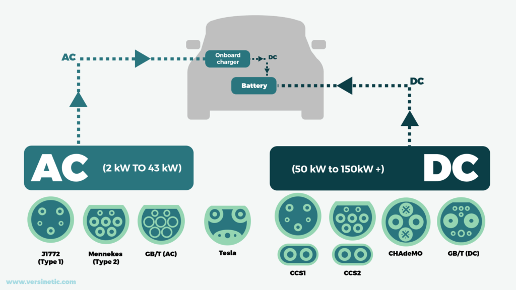
There are currently eight different connector standards in use, across AC and DC – varying from brand to brand and region to region.
The standards of the future are still uncertain, so be sure to research not only the current standard, but what the standard is likely to be in a few years’ time when choosing what to support.
Chargers can be created with tethered or untethered cables.
The former is more convenient generally, however locks the charger to a specific connector type.
Untethered options are more flexible, allowing the user to have a cable to match their car, however, this requires a locking mechanism.
In addition to the external cabling, there will be internal cabling which needs to be accounted for in the mechanical design, as the power requirements mean it can be bulky.
Electronics
At its most basic, an AC charger is essentially a power switch with communications between the vehicle and charger. Its chief purpose is electrical safety, with the ability to limit the power that the vehicle takes.
A very simple EVSE specification – as they are known – can be found at OpenEVSE. Versinetic’s EEL board is a commercial alternative to this.
The other key component required for a simple AC smart charge point is a communications controller, which are often found as single-board computers. Versinetic’s MantaRay board is an example of this. You can then complete a charging system with contactors and RCDs (AC and DC leakage) for safety.
Smart chargers add communications to the charger to allow the charger to join a cloud-controlled network.
The actual communications chosen is very dependent on the final environment of the charger. Some developers choose Wi-Fi or GSM, while in certain situations, wired standards such as RS485 or Ethernet may be preferable.
There may be extra boards to control displays, authorisations and more, depending on how sophisticated the system is.
This is an essential consideration when planning your EV charging system electronics.
The socket, relays and contactors will heat up when on full charge. This needs to be accounted for in the industrial design as heating can shorten component life. The socket it particularly vulnerable as it can be exposed to the elements and mating cycles will cause wear.
Environmental issues – wide temperature operating range
Will your EVSE be designed for use in temperature extremes? Standard commercial temperature range components are rated for 0-70 C, whilst industrial temperature range is -40 to +85.
Factor this in as early as possible in your development.
Step 6: EV charging system software
The software block of development requires conforming to multiple standards, and can be the most time-consuming section of the project.
The electric vehicle market is still young, relatively speaking, and therefore many standards and regulations are still changing and being updated.
Your charging system must have a reliable update provision system to cope with, as it is impractical to predict all the changes that are going to occur.
If you are planning a network of any scale, this will almost certainly have to be done using OTA (over-the-air updates).
This comes with extra security challenges – an increasing concern for EV charging system design.
EV charger software blocks
Firmware
The embedded software that controls the state machines that turn the charger on and off.
IEC 61851
The most basic communications protocol used in Type 1 and 2 AC charging systems between the charger and the vehicle. The information exchanged here includes when the charging starts, stops and the current the car draws.
OCPP
This is a global standard for charger communication with a back office, created by the Open Charge Alliance (OCA). The latest edition is 2.0.1, but basic smart charging can be achieved with OCPP 1.6.
Testing OCPP can be done as a service by the OCA or at OCA Plugfests, which occur 2-3 times a year, and enable you to test your system against back-office providers and the OCPP standard.
The OCPP specification has required and optional features, ranging from basic charger control to high-level security and reservations.
You will need to choose the OCPP level you require, alongside which parts of the standards you need to support for your application.
Web interface and app
Charger configuration and initial registration will need to be facilitated, both for the network manager and the installer. There are a variety of ways of doing this, but a web interface or app is common.
Supporting SIMs
If you are using a GSM module, you need to consider the geography of sales of the product as the GSM standards vary between continents and are currently undergoing changes as older standards are switched off (e.g., 3G) in favour of newer ones – such as LTE-CATM.
SIM contracts also need managing so that their expense is covered without inconvenience to the customer. Again, for SIM contracts, you will need to take geography into account.
Provisioning your charger
The actual deployment of the charger is a big part of the software effort, particularly if the charger doesn’t support a GSM connection and so needs to connect to a local network. How this is done can make a big difference in customer experience.
Note that the customer could be an end consumer or a professional installer, depending on the target market. For the consumer market, the charger needs to be simple to attach to a communications network and to monitor, e.g., from an app.
Security – what levels are you planning for your charger?
Security is a hot topic following IoT ransomware attacks and there is every reason to think that charging networks will be the target of future similar attacks given the damage such an attack could create.
The standard will vary with the geography of the installation.
Step 6: The software
Almost all smart chargers exist as part of a network. A couple of examples include Ecotricity and BP Pulse.
These chargers are all connected to a Charging Station Management System (CSMS), or a back office.
As a charging manufacturer, you can either choose to develop your back-office solution, or pay a licensing fee for a third-party solution.
Versinetic has partnered with Saascharge; other examples include Allego and has.to.be.
A CSMS enables:
- The commercialisation of charge points
- Load-balancing across chargers within a vicinity
- Remote control of chargers, using an app for example
- Interoperability between networks
- Monitoring of maintenance status
There are alternatives – such as locally controlled networks – which may be appropriate for private fleet charging, for example.
Other scenarios where local control would be useful include areas with poor signal, and networks where rapid load-balancing is a priority – for instance, where the power supply is unreliable.
Within the context of our hardware, the communications controller would likely have OCPP integrated, and later on when we explore DC charging, ISO 15118 as well.
Therefore, a key hardware requirement for the communications board is a microcontroller capable of handling OCPP and the other software libraries.
Step 8: Going the extra mile
Extra technologies to add to your charging solution.
It’s just a phase
Most charge points currently use single-phase power for charging; however, some charging systems make use of 3-phase power to increase charging rates.
For example, the Renault Zoe can be charged at 22kW instead of 7.4kW when using 3-phase.
Pros
This charging is clearly faster and can be achieved using AC technology, which – in some instances – will nullify the need for DC chargers.
Cons
Power supply and grid management are more of a problem: most domestic dwellings don’t have access to 3-phase power or the bandwidth for this rate of charging. 3-phase contactors and relays will also need to be integrated into the charge control design.
Only select vehicles currently support 3-phase charging, but this is set to improve as more electric vehicle models are released.
With great power comes great responsibility; there are extra regulations around how the phases are used, for instance, with phase rotation a requirement in Norway. As with all compliance, these regulations vary with region.
Need for speed
Time to address the elephant in the room… and talk about DC.
Within a DC charge point, much is the same as with its AC counterpart; however, the voltage and current are higher, starting at approximately 50kW.
When charging with an AC charge point, the charge controller is usually communicating with the inverter found in the vehicle that converts the AC power to DC power in order to charge the EV battery.
This inverter can only handle so much current, hence why AC is slower than DC charging.
With DC chargers, this inverter is in the charger instead, offloading an expensive and heavy part of the overall charger setup, to the pavement.
Communications standards are also different.
Connector Types
In the same way as AC charging systems have Type 1 J1772, Type 2 and more, DC charging systems have CHAdeMO, CCS and Tesla.
Recent years have seen CHAdeMO decline in favour of CCS, which has now been adopted by most western automakers. However, CHAdeMO has now formed an alliance with China, the largest EV market in the world, and South Korea seems keen to join.
This is to collaborate on the development of CHAdeMO 3.0 and the new Chinese standard ChaoJi, which can capable of charging at a power greater than 500kW, and is backwards compatible to CHAdeMO, CCS, and GB/T standards.
Download the full guide to connector types here
CHAdeMO also remains the only DC charging standard to have incorporated bi-directional power flow capability for V2G (Vehicle-to-Grid). And in the UK, V2G is likely to gain in prominence due to renewed interest by Ofgem, the UK’s energy regulator.
As an EV charger developer, this just makes it more difficult to decide which protocols to support.
The CHAdeMO protocol communicates via a CAN interface with the vehicle to control safety and transmit battery parameters.
The CCS connector is made up of either a Type 1 or 2 connector with an extra DC connection underneath. Therefore, basic communications are still done according to IEC 61851. High level communications are done using the extra connections, using DIN SPEC 70121 and ISO/IEC 15118. ISO 15118 enables ‘plug-and-play’ charging, where authorisations and payment are completed automatically, without any driver interaction.
These are significant software blocks that come as well as OCPP and IEC 16851 which impacts the extra development work for DC chargers, and this, combined with lower sales volumes and the higher BOM cost is reflected in the retail price, which can be up to £30,000, instead of around £500 for an AC charger.
Renewables all the way
In the not-too-distant future, more and more of the world will be powered by renewable sources.
In particular, some EV charging networks are now partially powering their solutions using Solar PV. It will increase your potential market if your solution is provisioned to use solar energy and other renewable sources. This will require, among other factors, having powerful load-balancing algorithms to account for the intermittent nature of solar power.
Leveraging local power
Coupled with solar provision is the ability for EV chargers to operate using locally generated power, solar or otherwise. The charge point can be designed to recognize different energy sources and balance them against each other to optimise cost and reliability.
Conclusion
Through the proliferation of initiatives to combat climate change worldwide, it’s clear electric vehicles and greener transport systems are the future.
However, the excitement at the opportunity afforded by the dynamic, fast-moving e-mobility market must be tempered with a careful, methodical approach to planning, development and delivery of your EV charging solution.
We hope you find this guide helpful in giving you insights into some of the complexities of creating your EVSE.
Whether you work with your own development team or an EV charging design consultancy like Versinetic, having a clear USP and target market, as well as being vigilant with your project and production management, will give you a great foundation for a successful route to market.
Need EV charging system software, hardware, consultancy, or a design upgrade?
Don’t get left behind in this fast-moving market – let us help you save development time.

Dunstan is the founder of EV charger design consultancy, Versinetic. He is a chartered electronics engineer who has been providing design, production support and consultancy to businesses around the world for over 30 years. Dunstan graduated from Cambridge University with a degree in electronics engineering in 1992. After working in the industry for several years, he co-founded multi-award-winning electronics engineering consultancy ByteSnap Design in 2008. He then went on to launch international EV charging design consultancy Versinetic during the 2020 global lockdown. An experienced conference speaker domestically and internationally, Dunstan covers several areas of EV charger design and electronics product development, including load balancing, V2G, IoT, integrated software design and complex project management.
In his spare time, Dunstan enjoys hiking and astronomy.